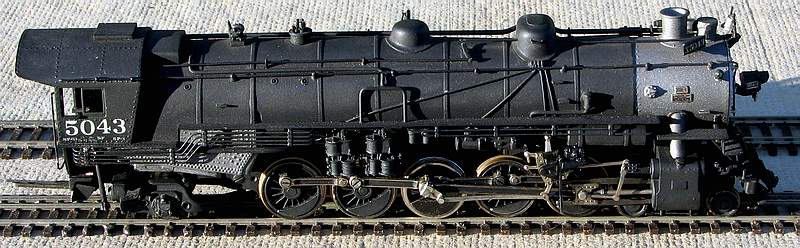
REPOWERING The MAX GRAY ESPEE SP-1 Class 4-10-2 |
| Model Photo |
|
| Model Information |
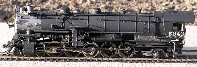
Brass HO scale model of the Southern Pacific three cylinder SP-1 class 4-10-2, imported by Max Gray, built in Japan by Katsumi (KTM). KTM models are among the most popular HO brass steam models. Even though most were imported with open frame motors, KTM models were well made with excellent mechanisms. While making models for Balboa Scale Models, KTM introduced the idler gearbox, also found in WestSide Model Company imports made by KTM. With addition of a new can motor and flywheel these KTM models run even better. Older KTM models like this KTM 4-8-2 can be updated by adding a new KTM idler gearbox along with the can motor and flywheel. Details on how I did the 4-10-2 below.
|
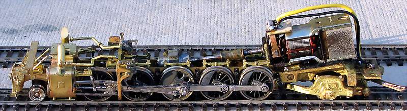
| The Mechanism |
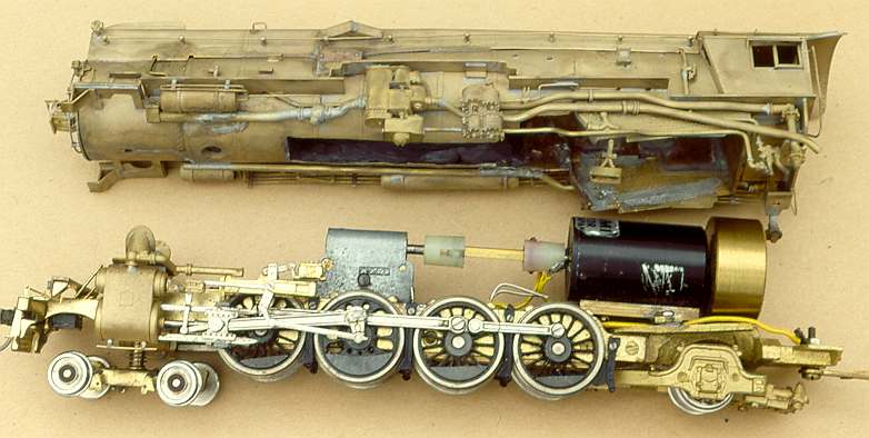
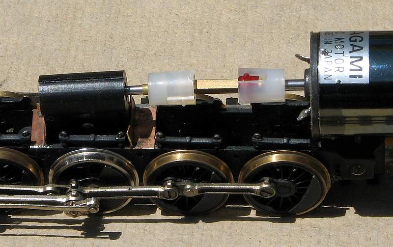
The KTM models used an assembled brass frame riding on coil springs on bronze bearings on each driver axle. Early KTM models had an enclosed non-idler gearbox, with typically a 27:1 gear ratio. Many large drivered engines might have a 37:1 ratio gearbox. A large KTM open frame motor provided dependable power, connected with flexible tubing to the gearbox. The flexible tubing also restricts movement of the gearbox, keeping it aligned with the motor shaft. While the tubing transmits power to the wheels, it also consumes a lot of energy keeping the gearbox aligned, raising current draw. The photos below show a non-idler gearbox mechanism connected to the open frame motor by a short length of flexible tubing. Note: the motor is mounted on an angled portion of the frame to align with the gearbox.
|
  |
| Diagnosis |
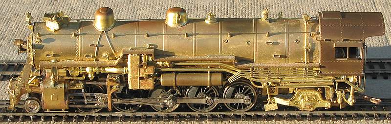
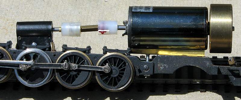
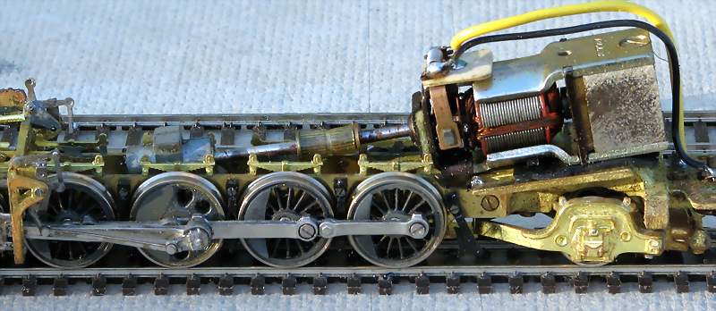
Non-idler gearboxes are not all the same; the KTM cast non-idler gearbox provides excellent gear alignment and allowed the use of sprung driver axles. This was a major improvement over rigid frame mechanisms and a worm mounted on the motor shaft, positioned over a geared axle without a case to hold the gearbox together. Replacement of a gearbox is warranted if the old gearbox is unusable or if a new gearbox provides an improvement in operation. In the case of this SP-1 the center driver has been replaced. The major work of replacing gearboxes involves the removal and installation of axle gears. The replacement driver needed an axle gear so this was an excellent opportunity to install a new gearbox to replace a well worn non-idler gearbox. Idler gearboxes have some advantages over the non-idler gearboxes during remotoring work. The level drive train, shown in the photo below, allows installation of a larger can motor than would be possible with the angled motor mount for a non-idler gearbox. The additional space can also be used to install a large flywheel to provide smoother running qualities. The high drive train allows the motor to be installed very close to the gearbox; with the use of single ended NWSL motors the motor shaft can be used for the worm in a gearbox with the motor mounted to the gearbox with a torque arm. With non-idler gearboxes it is typical to have to go to a smaller diameter motor to mount close to the gearbox without interference from the frame or drivers. Unfortunately smaller diameter motors typically have much higher speeds or less power than the motors that work best in a large model like the SP-1. To make this model the best it can be, it was decided to install a NWSL 2240 can motor, large NWSL flywheel and a NWSL 36:1 Idler Ball Bearing gearbox. The large can motor has plenty of power for all ten driving wheels even if the large boiler is heavily weighted. This powerful motor, coupled with the ball bearing gearbox and high gear ratio, allows this model to start heavy trains smoothly and quietly.
|
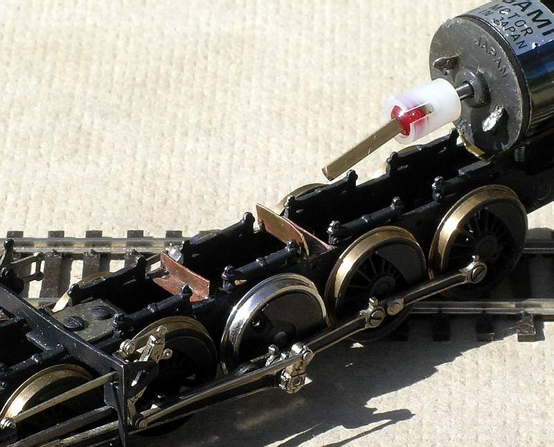
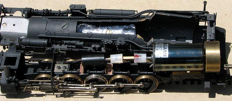
| Modifications - Installing the Can Motor and flywheel |
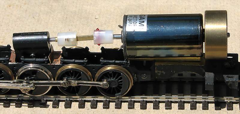
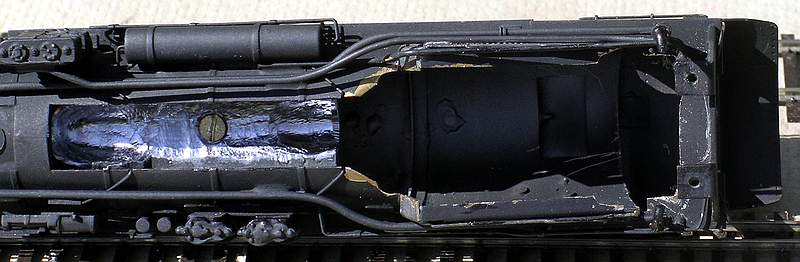
The motor shaft on this model is 2.4mm, a common size on Japanese models. This is also the worm shaft size of KTM gearboxes. NorthWest Short Line (NWSL) 2240 can motors also have 2.4 mm motor shafts. The original MG-KTM frame had a motor mount angles to align with the gearbox. This angled portion of the frame was milled off level with the bottom of the frame to allow the motor to be mounted level. Two motor mounting holes (2mm) were drilled thru the frame to attach the motor. The motor if mounted with a section of K&S channel running the length of the motor. Since one of the motor mounting screwheads might interfere with the trailing truck it was countersunk into the frame. The sides of the channel can be spread outward to lower the motor, if necessary. Extra length 2mm screws were used to attach the motor. They pass through the frame, brass channel and into the bottom of the motor providing a strong secure motor mounting system that allows for quick disassembly and replacement. Notice that the flywheel is mounted on the back of the motor. This puts the flywheel in the steam locomotive model's cab, where there is more room for a larger diameter flywheel. The larger diameter provides a greater "flywheel" or coasting effect to the model when the track voltage is reduced or interrupted. I no longer press fit flywheels onto motor shafts. Instead I use a NWSL hand reamer that matches the motor shaft diameter to achieve a tight slip fit and then use Loktite to secure the flywheel to the motorshaft. Oil the motor bearing before mounting the flywheel, apply Loktite to the hole on the side of the flywheel that will be away from the motor. This should prevent Loktite from entering the motor bearing next to the flywheel. Test the motor/flywheel combination before mounting by running the motor at various speeds while held in your fingers. The motor vibrations should be minimal, the same as they were before the flywheel was installed. The new motor, flywheel, and drivetrain are a different profile than the original KTM components; modifications may be necessary to fit the superstructure. Most of the work is enlarging the bottom for clearance for the large diameter motor and flywheel. I use a variety of tin snips, files and carbide Dremel cutting burrs. On models imported with idler gearboxes, the cast boiler weight has a notch to clear the gearbox. A similar notch was carved using Dremel carbide burrs. This is best done with the weight out of the model. If the lead weight rest on the gearbox, interferes with the universal drive, or the flywheel rubs on the superstructure, when tested your ears will tell you that you have more modifications ahead.
|
| Gearbox and Universal Drive Installation |
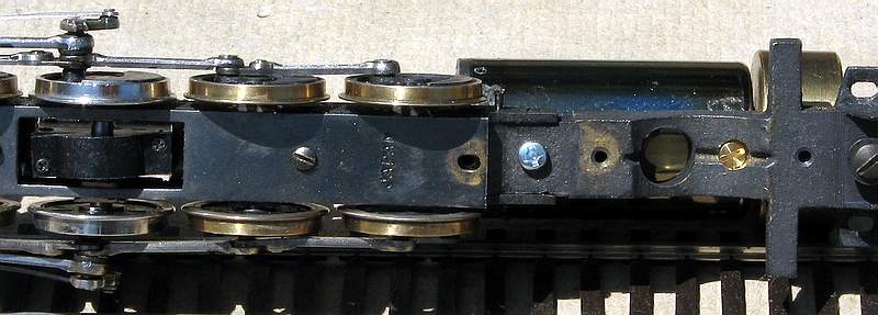
The NWSL ball bearing gearbox is one of the very few gearboxes that passes my "Dremel Test". I insert the worm shaft of the assembled gearbox into a Dremel motor tool. I then rev up the motor tool to full RPMs while holding it level. If the gearbox rotates with the motor shaft, making a 'wopping' sound like a helicopter; it fails the 'helicopter test. The NWSL ball bearing gearbox aces the test barely moving from a 6 o'clock position (hanging straight down) to a 7 o'clock position. A properly assembled KTM gearbox rotates to about 8:30, while most other brass import gearboxes fail. Because the new drive train uses a Hobbytown universal drive to connect the motor and gearbox, brackets have been added on the frame to keep the gearbox in alignment. The brackets a41 K&S 1/4" angle soldered to the top of the frame. With Delrin gearboxes you can't leave the gearbox in place when soldering the brackets to the frame. Test fit the gearbox first and then scribe the top of the frame to position the bracket when the gearbox is removed. Neoprene tubing connecting the motor and gearbox can be used to position the gearbox and brackets prior to soldering. KTM gearboxes do not have to be removed during installation of the brackets. A standard Hobbytown universal drive completes the drive train. The Hobbytown universal shaft size is 3/32nd", which is virtually the same as 2.4mm; the NWSL gearbox has an input 2mm shaft so a bushing was used to increase the shaft diameter to 2.4mm to mount the Hobbytown drive.
|
| Epilogue |
I have used several can motors in KTM models. For all but the largest engines I use a NWSL/Sagami 2032 can motor. Originally these motors had 2.4mm shafts and were more rugged and durable than flat can motors like the Canon CN2231. For smaller engines I used the Canon motor but recently switched to the Kato motor used in their HO diesels. The flat can motors have 2mm shafts and do not tolerate the larger flywheels I like to use as well as the 2.4mm shaft motors. For installations limited to small 16mm diameter flywheels these flat can motors are excellent. For the largest KTM HO steamers I prefer the hard to find KTM 2336 can motors; the NWSL 2240 is a good substitute as is the slightly smaller and less powerful NWSL/Sagami 2236 can motor.
|