Guide to Repowering and Regearing
Why Can Motors?
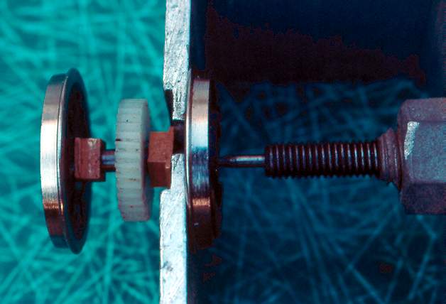
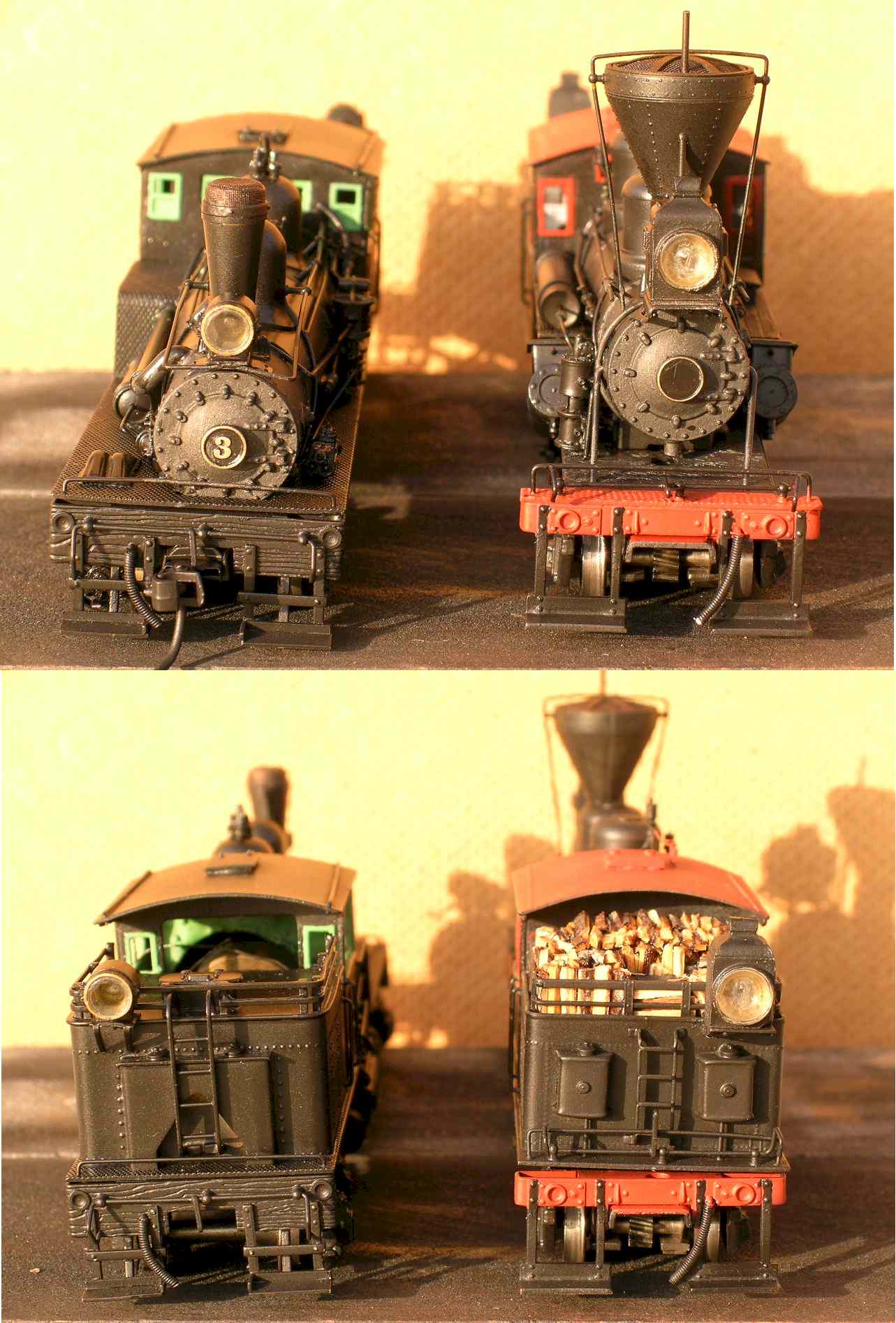
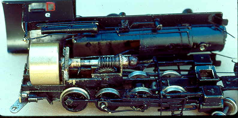
They save money. Compare the H0 steam locomotives imported in the early 1970's with those of 1980. The earlier models had fine detail, open frame motors, and were made in Japan. The l980's models have fine detail, can or coreless motors, and if made in Japan are very expensive. An example is a Westside Southern Pacific GS-6. The 1975 import with an open frame motor frequently sells in the after market for $300. The 1981 model has a coreless motor and a list price of almost $500. What are the differences? Inflation in Japan, more rivet detail (too much for some people), a few additional small castings, and the motor. The mechanisms are both excellent and with the installation of a Mellor motor the 1975 import (Fig. 1) can run better than the 1981 model. By adding a few small details along with a new motor, you can have a model that looks excellent and runs as well as any of the newer imports, and you same money.
Performance
This is a controversial topic. For the NMRA, performance judging is heavily dependent on motor efficiency, with running limited to clean straight track. For a club member, performance is smooth running without stalls and derailments on anything but clean straight track. The two standards do not always coincide. A Northern (4-8-4) scored a perfect 5 performance rating on the Motive Power Performance Review in the NMRA bulletin, yet had design flaws that would not allow sister engines to run through #8 switches, around 48" curves, over Kadee magnets, while frequently stalling on slightly dirty (typical Club) track. The can motor installation methods discussed can produce the performance needed for running on model railroads ("If it runs at the Club it will run anywhere""). Coreless or Micro-motors are better for NMRA-style performance contests where higher efficiency produces contest points. Also, a motor for performance contests needs a starting RPM to 12 volt no-load RPM ratio of about 20 to 1, while most can motors have about an 11 to 1 RPM ratio listed in their specifications. Do not expect a smooth running engine with a can motor and flywheel to score as well as engines equipped with coreless motors. An engine that runs at 3 scale MPH with a can motor will have a top speed of 35-40 MPH at 12 volts which may be way under the top speed of the prototype (but fine for running on most layouts).
Can Motors, Fact and Fiction
The use of can motors in model locomotives has created both interest and confusion. The benefits, low current draw, smooth starts, easy installation of flywheels, have made many converts. The drawbacks, high initial cost (compared to open-frame motors), installation problems, and availability have discouraged potential users. Most importers of brass locomotives are now using a can or coreless motor in their models. The stock of replacement motors maintained by some importers is a good source for motors.
Investigate the Sagami line of motors formerly imported by North West Short Line (NWSL). They offer the widest range of can motor sizes, double and single shaft models, and thanks to the efforts of NWSL, a complete line of repair parts, brushes, end caps, and armatures, was available. After an earthquake destroyed the Sagami factory, NWSL had to find another manufacturer; the new motors are sold as NWSL motors and are available in most of the sizes previously made by Sagami. This can be a salvation. If for any reason a brush or armature should fail, it can be simply, and cheaply, replaced (compared to a new motor). With non-Sagami motors you must simply buy another motor. If you make a mistake and cut the motor shaft too short, a new armature will give you another chance. The major disadvantage of Sagami motors was their popularity, NWSL had experienced problems keeping some models, notably the 1630 and 2032 motors, in stock.
These are the motors to use for H0 non-articulated engines. A simple guide for motor selection is: a 1630 for small engines, a 2032 for engines with drivers 63"" in diameter or larger, space permitting. Even though the Sagami Motor booklet indicates that 1630 and 2032 motors have similar 12 volt, no-load speeds, installation in the same engine has shown the 1630 to be considerably faster. Using a 1630 motor in small drivered engines may allow double-heading with engines having larger diameter drivers and a 2032 motor. It becomes apparent that standardizing motor selection can produce one, two, several, or a fleet of engines with very similar running characteristics.
Imagine a train headed by a Ten wheeler and Mikado with a 2-10-2 and an articulated cut into the train as helpers and with current draw at less than an amp. It’s possible with can motors.
Start by checking on motor availability. Some dealers, stock the complete line of NWSL motors and replacement parts, and other motors as well. If your dealer is out of stock, have him try Walthers or order from NWSL direct. If you decide to equip several engines with the same motor, it would be good insurance to have a spare motor or at least a spare end cap and armature for that motor. With the knowledge that the motors are available and that parts are available for repairs, installation can begin.
INSTALLING A CAN MOTOR SHOULD BE APPROACHED AS PART OF A TOTAL DRIVE TRAIN PROJECT. ALL COMPONENTS OF THE DRIVE TRAIN, MOTOR, FLYWHEEL, UNIVERSAL DRIVE, AND GEARBOX, SHOULD BE EVALUATED AND REPAIRED OR REPLACED AS NECESSARY.
Installation of the motor
Although can motors can be installed many different ways, the discussion will be limited to brass steam locomotives. The principles are similar for other types of locomotives, but in the case of plastic diesels it wasn't worth the effort to install a can motor in an Athearn diesel when for only a few dollars more you could let Proto Power West do all the work. Kato diesels use an excellent motor that can also be used in some steam models. The most difficult installation method is mounting the motor on a torque arm attached to the gearbox with the motor shaft extending through the gearbox (. This may provide the best possible performance, but the gains are slight compared to the effort and skill required.
Except in extreme cases, use the following simpler installation setup on the diagram:
Step One: Remove the motor from its package, turn the shaft to make sure it is free, connect to a DC power pack and run the motor. Holding the motor, it should feel like it is running free with little vibration. After a minute of running, record the current draw (if possible use a multi-tester with a range of at least .0 to 300 milliamps, 0 to 500 is better) at 12 volts.
Current draw should be in the range of .06 to .10 amps (check the motor specifications if available). This current draw will allow us to determine how much the mechanism affects performance. If your motor has an acceptable current draw, runs smoothly at all speeds, proceed to the next step. Otherwise, return the motor. NWSL and Sagami Motor specs have been available in catalogs; the link below provides info for some other motors I have tested.
Operating Specifications for Some Newer Motors
Step Two
: Mount a Flywheel. The combination of a can motor and a flywheel will get the best performance out of most model steam locomotives. It will get an engine smoothly over dirty track that would stop a smooth running coreless motor equipped loco cold. Other alternatives such as wipers, pickup shoes, clipper oil, etc. do not help when electrical contact is broken. A flywheel can move the engine over an electrical dead spot or smooth performance on track with poor contact/pickup. However, it will not help start the engine if electrical contact has been broken. Care must be exercised when operating a flywheel equipped engine, or else the engine can run off the end of a spur, run through a switch, run into a turntable pit, or participate in a cornfield meet.All these events have happened and would not have occurred without properly installed flywheels.
Steam engines need the benefits of flywheels at least as much as plastic diesels, so install one', or two', or three? The easiest flywheel installation is having someone else do it. Mellor sold a Sagami 2032 with a large brass flywheel mounted on it. The cost was $3.00 more than the list price of a Sagami 2032 alone. Since the flywheel costs $2.50 by itself, for 50 cents I used to let Mellor install the flywheel. Unfortunately this flywheel is so large that it only Fits large locomotives, generally large Mikes, Mountains, and Northerns, etc. If the boiler/firebox/cab width allows use of this flywheel, try it. NWSL now markets a similar flywheel.
0n smaller boiler engines use the Timewell flywheels. They are machined to the diameter of Sagami motors.
Timewell #120 is 16mm in diameter and is drilled for a press fit on the shafts of 16mm diameter can motors. Timewell #124 is 20mm in diameter and is drilled for a press fit on the shafts of 20mm
diameter (and larger) motors. Timewell #101 is a space saver. Although larger than the #124, it has a large recess machined in one end allowing closer mounting to motors or universal drives when space is tight.
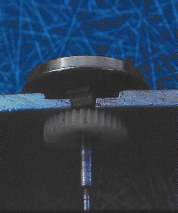
Use of a flywheel requires small modifications in most models. Flywheels and can motors are wider than most open frame motors they are replacing. This can require removal of some brass
sheet metal on the bottom of the cab, firebox, and possibly the boiler (Fig. 4). 0n large engines without backhead detail, modification is usually minor. Try to put the flywheel in the cab or next to the backhead to hide it from view. Try to leave the backhead in place if the model was imported with one, although removal of the backhead can simplify installation greatly.
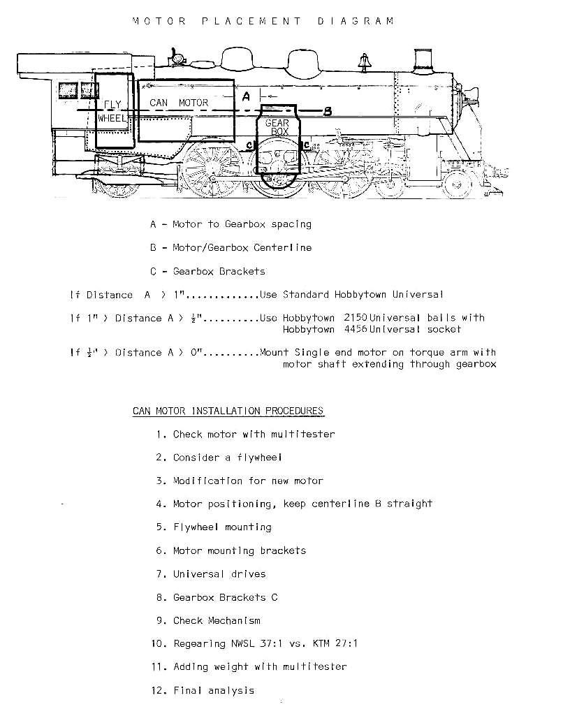
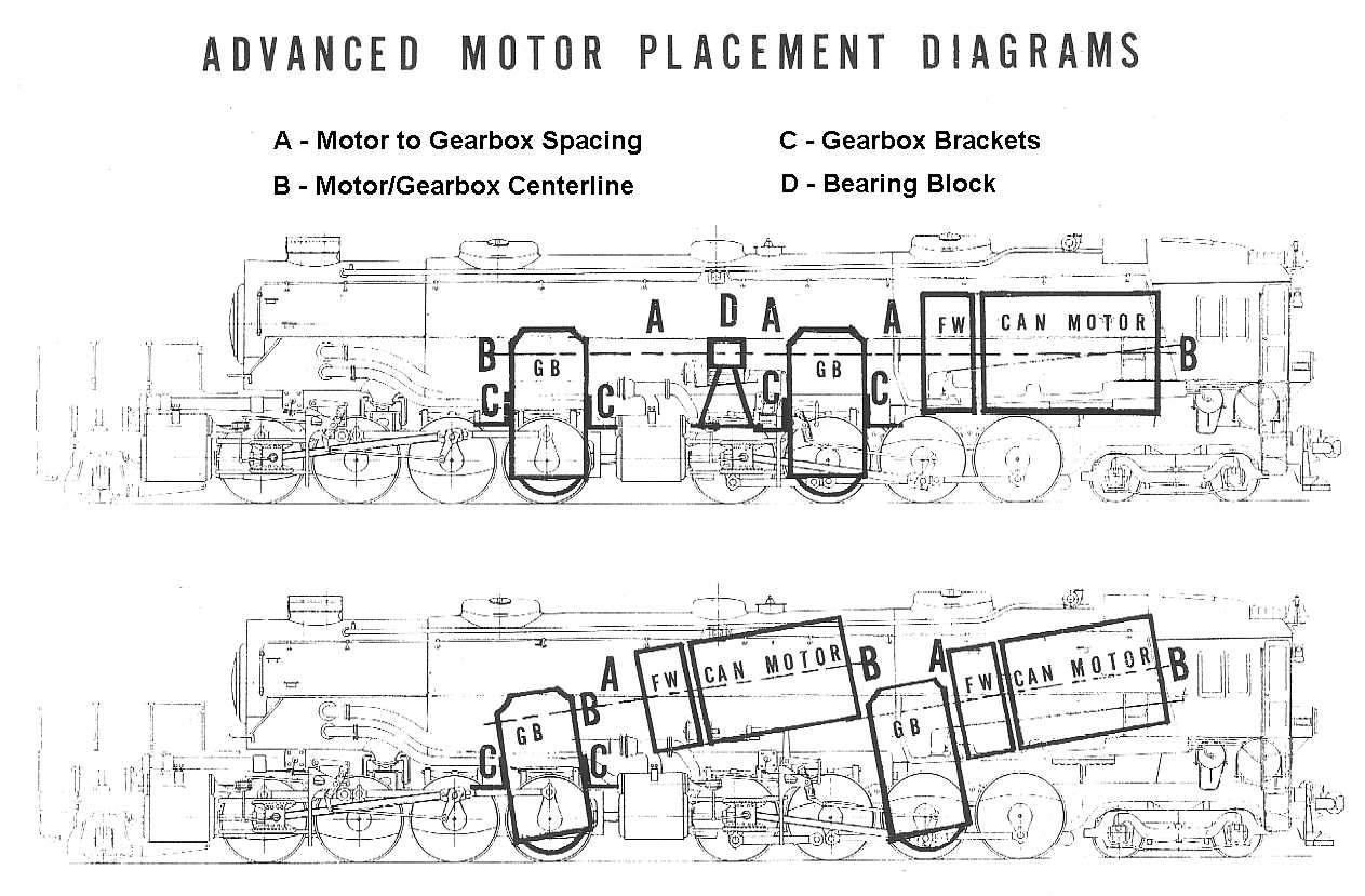
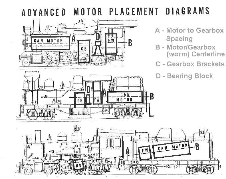
Now is the time to finalize installation plans. Place the motor and flywheel on the locomotive frame, allowing clearance for the back of the cab or backhead of the firebox . Referring to ( Motor Placement Diagram) measure the distance A, from the front of the motor to the rear of the gearbox. If distance A is less than l/2 inch, special procedures, such as torque arms, single shaft motors, use of the Timewell 101, are required. These will be discussed later. If distance A is between l/2" and l" you can use a Hobbytown universal drive consisting of universal balls 2154 and socket 4150. For distance A greater than l" use the standard Hobbytown universal drive. Other universal drives can work, but these seem the quietest and are easy to install. In all cases consider replacing the flexible tubing. If you have room for the motor and flywheel and distance A is greater than l/2", mount the flywheel. Follow the Timewell directions. If the press fit is tight, use a reamer to very slightly enlarge the hole in the flywheel. If the fit is loose, carefully put a drop of Locktite in the hole on the end of the flywheel away from the motor to keep it out of the motor. 0nce the flywheel is mounted, test the motor again. Holding the motor in your hand, it should not vibrate any more than the motor did without the flywheel. At slow speeds the flywheel should not appear to wobble as it turns. Now is the time to ensure that the flywheel runs true. Usually there is no need to attempt to balance the flywheel-armature combination, although it would be simple to do so at this time.
Step Three: Lining up with the Gearbox. For best results the centerline of the worm in the gearbox should match that of the motor/flywheel. The gearbox can be rotated around the axle to aid in lining up the centerlines. Normally, the open frame motor provides a mounting pad for the new can motor that is in line with the gearbox. Using the flexible tubing that came with the model, connect the gearbox to the can motor. Hold the motor as low on the frame as possible, keeping the shafts aligned. Again connect power to the motor and run the mechanism. Try a couple of different motor angles, observe the current draw. In a good mechanism the current draw may be .15 amps or less. It should not be more than .20 amps. (If it is, the mechanism requires tuning.) Having determined the best motor position check to ensure that the mechanism and superstructure allow room for mounting. In those engines not having Idler gearboxes, it may be necessary to file down or remove the leaf spring castings above the rear drivers. Idler gearboxes allow mounting the motor horizontally, straight into the gearbox. If the mounting pad on the frame is long enough to allow positioning of the motor, then the motor can be shimmed with brass strips and Neoprene pads to line up with the gearbox. When the proper amount of shim is determined, it is finally time to mount the motor. I have used Silicon Sealer to mount motors, but prefer to use machine screws to allow easy and quick installation and removal. Having positioned the motor on the frame, forward of backhead or cab end, scribe two lines across the frame (Fig. 101 to line up with the mounting holes on the motor. Scribe a line down the centerline of the frame (top side). Drill the two motor mounting holes where the lines intersect. Using the holes in the frame, mark (with a punch) the shims to be used and drill them also. Attach the motor with the screws provided. Use the flexible tubing to connect the motor and gearbox. If the shafts touch, shorten one with a cutoff disk but be sure to leave at least l/4" of shaft for attaching the universal drive. Again connect power and run the mechanism. Look for binds, check slow speed operation, check current draw. A good mechanism will add less than .05 amps to the no-load current draw at 12 volts. An added load of over .1 amps indicates a poor mechanism or a poor job of motor mounting.
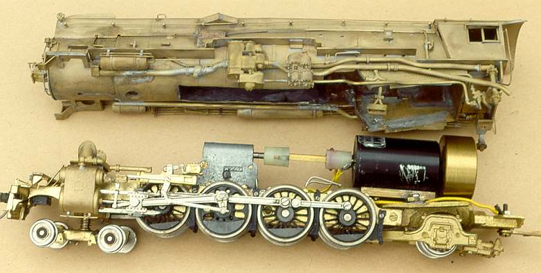
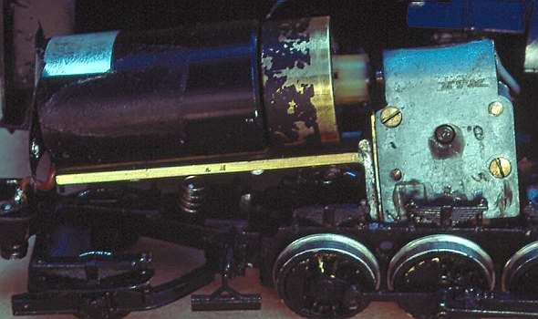
KTM SP Mt-1 - Remotored and Regeared
. Step Four. Motor mounting brackets can be fabricated in many shapes. The most common bracket used in imports is an end mount made of sheet brass. End mounting of the motor making installation of a flywheel difficult with this bracket. The strength of this motor mount is dependent on the thickness of the bracket, the design is not inherently rigid. This bracket is used because it allows quick installation of the motor from above the frame. Use of flywheels generally requires rigid mounting brackets designed for bottom mounting.
The simplest bottom mounting bracket is a piece of inverted brass channel, K&S l/4" channel, cut to the length of the motor and attached to the frame. This mount allows simple adjustment in the height and centerline of the motor by spreading the sides of the channel, is strong due to its shape, and holds a can motor very securely. Attachment to the frame can be by solder, epoxy or screws. This bracket is especially useful when the motor mounting pad on the frame is not long enough to align with the mounting holes on the motor .
Step Five.
. Improving Performance.
Except for wiring, the remotoring job is finished unless you want to improve performance again. Replacing the motor is a big step towards better performance. The next step is easier. The flexible tubing connecting motor and gearbox is usually a poor transmitter of power. If you had an increased load of more than .05 amps the flexible tubing may be the culprit. Replace it with a Hobbytown Universal Drive (or equivalent). It is a simple operation with one slight problem. The flexible tubing also prevents the gearbox from rotating around the axle. The universal drive allows the gearbox to rotate so that gearbox must be held in position aligning the worm shaft centerline with the motor/flywheel centerline. This is done by using K&S 3/16 angle stock, attached to the frame. Solder the brass stock to the frame. ACC or epoxy might be used, but the frame is usually greasy or oily and must be cleaned for a good bond and care must also be taken to keep any glue out of the mechanism. Remember to remove the plastic brake shoes before soldering. In the photo of the Mt-1 above, a bracket can be seen behind the gearbox, on top of the frame.
Step 6: Slowing the Engine Down.
By now you should be able to see a marked improvement in the performance of the engine. If the mechanism is free running, you should be able to pick up the engine while running and see the drivers revolve as they slow to a stop. On the track the engine should slow down and stop smoothly, it should no longer stop on a dime. Enjoy the fruits of your labor, then consider some operational possibilities. If you were a Southern Pacific modeler and had replaced the open frame motors in a Westside GS-4 and GS-6 with Mellor motors you might be surprised to see that the GS-4 ran noticeably slower than the GS-6, even though it has larger drivers (80" to the GS-6's 73".
If you also installed a Mellor motor in an SP F-5 (2-10-21 with 63" drivers you would be more surprised when it also ran faster than the GS-4. 0n very few prototype railroads do high wheeled Northerns have lower top speeds than drag freight engines. The problem is that the GS-4 models were equipped with a KTM 37:1 gearbox while the other models mentioned have KTM 27:1 gearboxes. Engines with drivers 73" or larger can be equipped with the KTM 37:1 gearbox (See GS-2 below). Engines with smaller drivers have to be regeared. NWSL Part 104-06 was a package of polished 37:1 gears for use in the KTM 27:1 gearbox case. They are a quality product and well worth the trouble of installation. Many a poor mechanism is just that because of a poor or worn gearbox. Current draw in a used Alco Mt-2 (with factory installed Sagami 2032 was cut in half by installing a KTM 37:1 gearbox. If a mechanism rolls freely on a level surface with the gearbox removed, yet runs poorly with high current draw when the gearbox and motor are installed, check the gearbox.
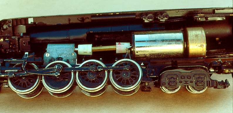
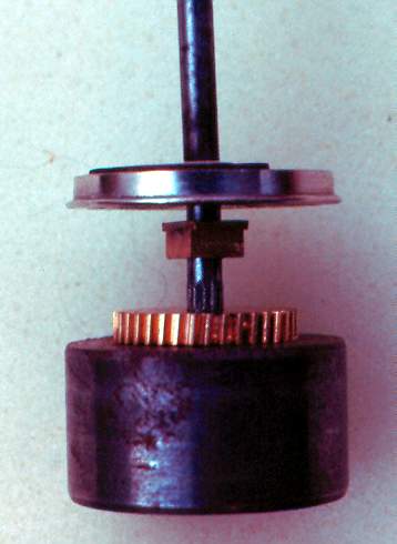
KTM SP GS-2 Mechanism - Remotored and Regeared with KTM 37:1 Gearbox
Gearbox performance can be easily checked, complete disassembly is not required. The axle gear can be visually checked for burrs, worn teeth, particles wedged in the gearteeth.
If the mechanism and gearbox binds or slips once per revolution of the drivers it may be the axle gear. If the problem is irregular, then it is in the gearbox. Remember all bearing surfaces must be smooth and clean. In an idler gearbox there are three (31 turning shafts, the worm shaft, worm gear shaft (idler gear) and reverse worm gear shaft (axle shaft), with six (6) associated bearing surfaces. Something as innocuous as painting a gearbox can cause it to freeze up if the paint enters any bearing surface. The performance of an idler gearbox can be checked by placing the worn shaft in a Dremel motor tool. If the gearbox does not revolve when the Dremel is run at varying speeds up to full power, the gearbox passes. New gearboxes and regeared gearboxes can be run in with this procedure. If after a few minutes of running the gearbox still does not pass, disassembly is necessary.
The idler gear should be checked, when placed in either side of the gearbox with the worm removed, it should turn freely. If the gear does not turn freely, carefully ream the idler gear bearing hole, work slowly, checking frequently, stop when the gear turns freely. The worm shaft should be free turning in its own bearings. Install thrust washers between the worm and bearings so that the shaft slides only very slightly back and forth when placed in the gearbox. Excessive play along the worm shaft can cause the locomotive to stumble or jerk when running downhill with a train.
If all other bearing surfaces are clean and free of burr's, reassemble and retest the gearbox.
Major gearbox problems such as worn out or off-center bearings, worn or broken gears or bent shafts require replacement of the defective parts or a new gearbox. Such repair work uses the same procedures outlined above.
The final gearbox component is the axle gear. Removing the axle gear requires a gear/wheel puller. Always remove the non-insulated driver. On the axle end and driver scribe reference marks to aid in alignment during reinstallation. I have found that two lines scribed from the center out are easier to realign than one scribed all the way across the driver hub. . A quartering jig is not needed if the scribed line is not eliminated during the removal process. After removal of the driver with a puller, remove the bearing next to the driver. Measure and record the distance from the insulated driver to the axle gear. Pull the axle gear, press on the new axle gear until it is spaced the same distance from the driver as the original gear.
Reference Marks on Non-Insulated Driver
Non-Insulated Driver Removal
Axle Gear Removal
Non-Insulated Driver and Axle Gear Removed
The NWSL aligner is a simple inexpensive tool that will press on the axle gear perfectly square. NWSL used to sell these in pairs, but I only use one of the two. I have three sizes, 3mm is for most imported HO brass, 2.4mm is for most HOn3 brass, 1/8 inch for US made locos; A 2mm aligner is also available for daring souls in N scale. I use a drive pin slightly smaller than the axle diameter to press on gears as shown in the photo below.
NWSL Aligner - In use with Drive Pin on Axle
Line up the non-insulated driver with the reference marks on the axle end. Press on the driver and reinstall in the mechanism.
The mechanism should be free rolling in both directions. If it is not free rolling, quartering adjustments can free the mechanism. This is done by visual counterweight alignment - try turning the axle gear, stop when binding in the mechanism occurs. When this happens look at the counterweights . If the driver counterweights do not line up on each side of the engine, a driver is out of quarter (relative to the others). The geared driver will lead (rotational angle) the other drivers an equal amount when turning in either direction. If the geared driver is out of quarter relative to the other drivers a slight correction can be made twisting the non-insulated driver along the axle. Carefully twist the driver in the direction to correct quartering. Check both sides of the engines for visual counterweight alignment. I stopped using the NWSL Quarter when I realized that not all drivers were in exact 90 degree quarter, but as long as all were quartered the same the engine ran fine. Visual counterweight alignment is a good method for locating mechanism binds while running on the layout.
Step 7. Improving Tractive Effort
The use of a can motor seems ideal for model steam engines, a round motor in a round boiler. Changes in motor location and mounting may affect the model's pulling power. Having finished with the mechanism improvements, we can now address a major problem in imported engines, lack of weight, or unbalanced weight distribution. Addition of weight may double the weight of a model while making it more susceptible to damage during shipping. Since importers pay for shipping by weight, it should not be surprising to see models with only small weights included, almost enough to balance the motor at the other end of a model. Adding weight is simple enough as long as the model remains balanced at the center of the drivers. If the model has a sprung 4 wheel lead truck, the center of balance should be forward of the center of the drivers to compensate for the lead truck spring. Otherwise the lead truck spring may lift the first drivers off the track, leading to derailments. Addition of weight is limited by the space available and the current load on the motor. Some locomotives with coreless motors do not have boiler weights, because addition of any weight can overload the motor and burn it out. With Sagami can motors the load limit should be the maximum continuous current load listed in the motor specifications. Using a multitester or 500mA Ammeter, record the current draw at 12 volts with wheels slipping. As long as the full wheel slip current is less than the maximum continuous load, the motor will not be overloaded. More weight may be added if space and current load permit.
Step 8. 0peration, Lights, Action
After completion of the motor/drivetrain/gearbox overhaul, the model can be test run. If all the steps were followed, there should be noticeable changes. Use of a can motor and flywheel should make the locomotive run quietly and smoothly. A frequent source of noise is the drivetrain rubbing inside the boiler weight or boiler shell. Remove any interference. Wheel noise may now be very noticeable due to a quiet motor and additional weight on the rails. After prolonged use, another change can be seen, pickup wheels will not get dirty as fast as before. Daily wheel cleaning should become a thing of the past. There is only one drawback to can motor installation, it's difficult to stop after the first successful installation. Fortunately NWSL no longer ships motors in boxes, they just stack up too fast.
Lighting in Geared Engines is Simple and Effective
Most operators like to also add working headlights to their models. During the repowering project adding lights is the simplest it will be. I use 1.5 volt micro-bulbs mounted in a hole drilled in the brass headlight. Next I find the largest drill bit that fits inside the headlight and hand turn it in a pin vise to polish the inside of the headlight. The bulbs are mounted in Micro-Klear. Using a hole punch on sheet acetate I make a headlight cover also held in place by Micro-Klear. The result is an effective warm glow headlight. Two truck Shays and Climaxes don't have headlight wiring complicated by tenders.
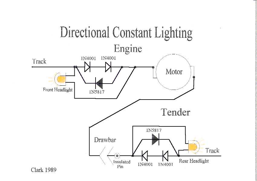
There have been numerous lighting diagrams published. The one I use, Trick Lighting Circuit, provides directional headlights without any additional connections between the engine and tender other than the drawbar. The use of Schottky diodes keeps the lights dim in the reverse direction, and the insulated drawbar pin allows the tender lights to be completely independent of the engine wiring. The Drawbar pin screws into a brass plate. The plate has an insulation backing and is held in place by nylon screws. It's simple and has been reliable.
Simple Directional Lighting Using Schottky Diodes
Insulated Tender Drawbar Pin
SPECIAL INSTALLATIONS
1 . Torque-Arm Motor Mounting
The most frequent special installtion occurs when there is not enough room for the universal drive between the motor/flywheel and the gearbox. This requires mounting the motor on a torque arm attached to the gearbox with the motor shaft running thru the gearbox. For the details of torque arm motor installation, refer to "A Torque Arm Drive for Steam Locomotives", Model Railroader, November 1980. Success in torque arm installations depends on the same techniques discussed previously. Before installation of the torque am, run the motor at 12 volts D.C. Since the motor shaft extends into the gearbox (the worn is on the motor shaft) in these installations, the gearbox should not revolve around the motor shaft and the 12 volt current load on the motor should not increase more than about forty milliamps (.04 amp) (compared to no load out of box test). These are similar tests to those on standard installations. After installation of the torque arm and mounting the motor on it, again test the motor/gearbox at 12 volts D.C.
The current load on the motor should be unchanged from the previous test. Increases in the motor current indicate misalignment of the motor to the gearbox that will increase motor and/or gearbox bearing wear, resulting in premature failure.
WSM SP Mk-10 Torque Arm
The torque arm in the photo is soldered to brass angles held inside the gearbox by screws; the motor was attached to the torque arm and then the torque arm was soldered to the gearbox. The inside lip of the gearbox was machined in a mill to remove the thickness of the brass angle stock. The short Hobbytown universal is used between the flywheel and the gearbox. Many of these large flywheels are machined with a recess for the universal ball or socket.
Properly installed the torque am installation is the most efficient, eliminating friction losses in the universal drive or flexible tubing. Unfortunately, proper installation is much more difficult and critical than a standard installation and the benefits (other than compactness) are slight, with reduction in current draw less than 10 milliamps in the best instances.
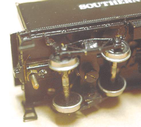
2. Tender Drive Installation
Southern Pacific #9 - HOn3
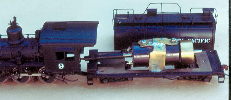
This is perhaps the easiest of the can motor installations. Advanced Motor Placement Diagram
Most tender drive models already have a gearbox mounting that restricts movement around the axle and use a universal drive between the tender and gearbox. All that is required is mounting the motor and flywheel in the tender. Most tenders have room for a 1630 with a Timewell 120 flywheel in H0n3 or a 2032 with a Timewell 124 flywheel in H0. Because can motors do not display as much cogging as open frame motors, tender drive can motor installations do not twist or turn the tender as much as open frame motors. 0ther benefits of tender drives include more weight over drivers with the motor in the tender, the same motors can be used in large and small engines. Consider an H0n3 example. The WSM D&RGW K-37 2-8-2 was imported with an open frame motor and idler gearbox. The PFM SP#9 4-6-0 was also imported with an open frame motor, but due to boiler size the motor was mounted in the tender. Both have 45" drivers and 28:1 gear ratios. A 1630 and 120 flywheel will mount in the boiler of the D&RGW K-37 or the tender of the SP#9. It never happened but the modeler can doublehead SP Tenwheelers and Rio Grande Mikes if both models have 1630 motors.
In standard gauge the possibilities increase. Consider Southern Pacific locomotives. Espee has Moguls, Tenwheelers, Mikados, 2-10-2's, 4-10-2's, 4-6-6-2 cab forwards, 2-8-8-4's, and 4-8-8-2 with cab forwards all having 63" drivers. Using two 2032's in the articulateds and tender drives in Moguls, you could have Moguls as point helpers for cab forwards. Espee did it, so can you (and a tender drive).
3. Articulated Engines
PFM United Articulated Mechanism - Stock and Noisy
PFM/United Mallets and Articulateds are known to be excellent runners with extremely noisy gears. The Noise is not from the gearboxes, but from the spur gears that lower the drive train from the motor to the non-idler gearboxes. Installation of idler gearboxes, which eliminate the need for the spur gear tower, quiets these models wonderfully. The top Diagram shows a typical installation.
Articulated Models - Motor and Gearbox Diagrams
With ball and socket universal drives, it is possible to mount the motor in the smokebox/boiler and connect the universal drive to the mechanism when attaching boiler to frame. This is especially true for articulateds which normally have some form of universal drive connecting the front (pivoting) and rear (rigid) engines. Aside from matching speeds with non-articulated engines having the same gear ratio and driver size, the benefit of two motors is realized with a sound system and sound cams on each engine. The two engines will slip in and out of sync, just like prototype simple articulateds. Since Mallets have only a single set of exhausts and the engines run together, two motors would be unprototypical for Mallets. For WSM AC-6's and AC-12's with cab interiors the rigid engine can be powered by a 2032 with 124 flywheel on a torque arm gearbox. The pivoting (swinging) engine is powered by a boiler mounted 2032 with 124 flywheel.
There is very little room remaining in the boiler. With the torque arm mounting the rigid engine will run freer, but due to greater weight on the drivers, the rigid engine runs slower than the pivoting engine breaking the synchronization of the two engines. The sound effects are distinctive; you will like it or hate it.
WSM SP AC-6 Torque Arm
The torque arm in the photo is soldered to brass angles held to the gearbox by screws; the motor was attached to the torque arm and then the torque arm was soldered to the gearbox. The motor is a single shaft Sagami 2032, note to extend the shaft through the gearbox bearings part of the gearbox was removed, including one screw.
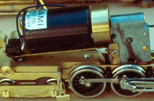
WSM NCNG #9 - Motor in Smokebox
Very small engines can present motor mounting challenges. The builder installed an open frame motor that stuck out the back of the cab on this little HOn3 2-8-0, the worm was mounted on the motor shaft. I put the worm on its own shaft, supported by bearings front and rear. I beefed up the rear bearing so that I could install a large flywheel in the cab. The 12mm coreless motor is in the smokebox connected to the wormshaft by the small Hobbytown universal barely visible in the boiler above the pinned ball on the worm shaft. The coreless motor runs at 5K rpm at 12 volts, this model is an exceptionally smooth low speed runner. Note the sound cam on the second axle; slow speed exhaust sounds were excellent.
Troubleshooting.
Generally in models with enclosed gearboxes, metal or plastic, if there is a dramatic
change in running between forward and reverse, it is one of two things, a driver out of
quarter, or excessive movement in the worm shaft though the gearbox. Most wormshafts are
either 2mm or 2.4mm(3/32"), older models are almost always 2.4mm, newer Korean
diesels are usually 2mm. NWSL makes thrust washers, both 2mm and 2.4mm inside diameter are
available, that can be placed on the shaft on each side of the worm to reduce end to end
play. The worm shaft should not move, other than rotate, in the gearbox, excessive end
play or worn bearings can result in poor gear mesh resulting in noise and poor operation.
Out of quarter drivers are much harder to correct. Generally the geared driver leads the
other drivers (turns first in the direction of rotation). The amount of the
"lead" should be the same in both directions, an out of quarter geared driver
will lead much more in one direction than the other. The easiest way to check this is to
observe the counterweights of all drivers, on both sides. This visual check is probably as
accurate as using the NWSL Quarter (I've had one for 33 years, it's been in the box for
the last 30).